Members Login
Username 
 
Password 
    Remember Me  
Post Info TOPIC: swapping generator for alternator


ST MARYS, ONTARIO

Status: Offline
Posts: 1415
Date:
swapping generator for alternator
Permalink  


 Catalog Ordering & Shipping Electrical Tech Work Shop Tips About M.A.D.

 click on the eletrical tech section..from there you can search around..


-- Edited by fatchuk on Sunday 12th of May 2013 11:07:18 AM

__________________


ST MARYS, ONTARIO

Status: Offline
Posts: 1415
Date:
Permalink  


This page attempts to document some of the common details and facts you need to know about when converting the existing charging system on your older GM vehicle to something newer and (hopefully) better. This information comes out of my research and work on upgrading my 1958 Buick Special from a generator to an alternator and from my previous work on the High Amp Alternators for older GM's article written while working on my 1973 Buick Electra. It is not a step-by-step guide, but rather a roadmap of important things to consider and be aware of. You should read my article on Alternator and Generator Theory before delving into this as it has lots of good details and basic cautions that will help you understand the details in this article. It's a tad heavy on theory, but once you understand why the system does what it does, then the wiring makes perfect sense and it becomes very easy to figure out what you need to do on your vehicle. Before actually tackling any physical wiring, you should take the time to read the suggestions outlined in my Reusing Plastic Wiring Plugs article for ways to get a cleaner appearance to your wiring efforts. Also, the information here would be of use to someone who wanted to convert the electrical system on a non-GM vehicle, but how much of this is accurate is up to you to decide. Also, if you own an older Buick with the "push gas to start" feature, check out my page on preserving this feature after you convert from a generator to an alternator.

There are three kinds of upgrades you can do. You can go from a generator to an alternator, from an externally regulated alternator to an internally regulated alternator, or you can take the monster leap and jump from a generator all the way to an internally regulated alternator. I detail all three separately, see below. Before tackling them, you should give my GM Alternator Identification page a quick look to see what the visual differences are.

A conversion like this has two basic pieces to it - mechanical and electrical. You need to mount the new alternator so that it's secure and you can put a belt around it and then you need to wire it up so it actually does something when you spin it.

This is a non-trivial upgrade to your vehicle. It's not that hard, but it could take some time to get right. Don't expect to have the car back on the road the same day you take it all apart. This is not an afternoon job for most home "shade tree" mechanics, although some of the easier conversions can be done fairly quickly. There are also commonly available kits to convert from an externally regulated alternator to an internally regulated alternator - shop around to see if you can find one as it will make your life much, much easier.

Mechanical Details

If you are swapping out a generator, your hardest challenge will be finding brackets to mount your new alternator. Unless you have access to custom built brackets (or are good enough to make them yourself), you need to get ready-made units from somewhere. Since GM has produced lots of motors with generators, I can't even begin to list aftermarket suppliers for them - start hunting around and see what you can find. My other suggestion is to find out if your motor was produced in some form after 1963 (that was the first year for alternators in GM vehicles) and try to scavenge brackets from a later motor. Whatever you do for brackets, you'll need to make sure it's all secure, that you can adjust the alternator belt properly, and that all the pulleys line up. You may need to put new pulleys on your crankshaft and water pump in some cases - check carefully and get this parts right. Other than that, there's not much I can say here - this is the ugliest part of the problem to solve.

If you're running a Buick Nailhead engine, see my page on Nailhead Alternator Brackets for more specific details and suggestions. If you're running something else in your ride either convert to a Nailhead engine or you're on your own for brackets. You can also try aftermarket sources if you're running a popular motor - check the ads in a magazine like Rod and Custom to find suppliers for some really odd parts. You can find places that will sell you the right brackets to run a GM alternator on everything from an early Ford flathead to an '50s Chrysler "Baby Hemi" engine - most of are done in chrome or polished aluminum too.

One thing of note to look out for is that later model GM alternators switched to metric threads and a metric sized bolt for the top mounting adjustment bolt. If you try to thread in a standard size bolt, it will act like it's been cross threaded, but it might just hold once. Or even twice. But it will strip out and cause problems. Either use the right metric bolt and always remember to use the proper metric wrench on that one bolt - or just get an earlier model alternator with the standard bolt threads on it.

If you are converting from an externally regulated alternator to an internally regulated one, well, your life will be much easier. Snag any first-generation internally regulated alternator (from around '73 to '85) and it will bolt right on in place of your existing unit. You can even swap the pulley and fan over to the new one if you need to. This is as close to a bolt-in as it gets.

At this point, I'm assuming you have a way to mount and adjust your new alternator. Put it in, but leave the adjustment bolts loose so you can move it around and get to the wiring while you work on it. After the wiring is done you can snug up the fan belt, tighten everything down, and fire it all up for a test drive.

Electrical Details

This is the part that most people freak out about. Many people think electricity is a mysterious and evil creation that must be feared. It's not that bad. Really! Just take your time, think about what you're doing, and it won't bite you (much). Plan out where all of the wires will go, make sure the battery is disconnected while you work on the wiring, and connect all of the wires to the right places. There really isn't much else besides that. Except all those little details, that is...

The first thing you need to do is figure out what you're going to do with all those wires. You sketch it all out on paper and make sure it at least looks like it ought to work before you dig in and start clipping and crimping.

I highly recommend that you get a wiring diagram of the charging system for both your existing vehicle and the vehicle you are using as a reference, then make a copy or two of each one so you can write on them, takes notes, etc. You want to merge the two diagrams together so that the result contains the pieces of the newer one grafted into your existing wiring diagram. Typically, you will want to keep one or two reference points on the old diagram and build the merged one from there using the new one as a guide. These points will be any wires that go from the existing charging system to the rest of the car - the power to the car itself and the battery, and perhaps the charge warning light or other similar wiring if they exist already. If you need to add new wires, that's fine too - just get it all there with things hooked up to the same conceptual places. Below are three sample wiring diagrams I have copied from various manuals to use as a basic reference. Also, if you are upgrading your system from a low-power alternator or generator to a higher power unit, you must pay attention to the size of the main feed wire that connects the alternator to the larger battery cable - the higher maximum power output could be a source of trouble if you don't take care of this.


Typical 1962 and Earlier Buick Generator Wiring


1963 to 1972 Buick Externally Regulated Alternator Wiring Overview


1973 to 1985 Buick Internally Regulated Alternator Wiring Overview


About now, you'll need to start figuring out where all these wires will go to on the car itself. Some things are up under the dash, some are under the hood, some are over on the fender by the battery - but they all go someplace. The schematics you made copies of and marked up to merge things together probably don't look much like an actual wiring harness - and that's because they're not supposed to. They help you figure out the circuit electrically - laying out the physical wiring harness is something different entirely, and that's what you need to do now. You may have some existing wires to reuse, or perhaps you need to remove them entirely. If you need to get wires from under the dash, out through the firewall, and to the engine, now is the time to figure out how. If you will have wires running between an externally regulated alternator and the alternator itself, you can reuse the two old generator to regulator wires and add the extra ones you need. If using an external regulator, mount it in the same basic place that the old regulator was at - it's got most of the right wires there already for you to hook up to. Now you can re-work your merged diagram some more to show what existing wires will get hooked up to what new things, what new stuff needs to be added, and if needed, what wires need to be replaced with larger ones.

At this point you should know what parts you need (wire, terminals, connections, etc.) and be able to make a basic run to the parts store. If you've done wiring before, you should have lots of spare bits and pieces laying around to help you out. If you've never done wiring work before, expect to make a few trips to get the various little pieces you need to get the job done. Some of the parts are a bit odd and may require some hunting.

If you need to add a resistance wire (because you are converting from a generator) you will need to hunt down the right resistor, or pirate the full length of the special resistance wire from a donor car in the junkyard. If you opt to get it from a junkyard, you must get the entire length of the resistance wire - if you cut it too short, it will be rendered useless for your needs because it will not have enough resistance in it. For example, if 6 feet of that resistance wire has a total of 10 ohms of resistance, 3 feet of that wire will only have a total of 5 ohms of resistance, and that's not enough for what you need. You can verify this resistance with a special "multi-meter" electrical tester that is available from places like Radio Shack for around $20. (Ask for one that can test voltage and resistance.) While you're at Radio Shack, you might want to just buy a 10 ohm/1 watt ceramic resistor and use that in place of the factory resistance wire, but you'll have to figure out how to mount it and hook it up. You can also use an ignition resistor if it's about 10 ohms - they already come with nice mounting points and easy to hook up terminals. It's your choice - as long as you put about 10 ohms of resistance into that one wire in the diagram and the resistor you use is rated for enough power to not overheat and melt, it'll work just fine. I'm told by my readers that a Radio Shack 10 ohm 10 watt 10% wire wound ceramic resistor (part #271-132) has worked well for their GM vehicles. Your mileage may vary, but if your system is similar to the system described here, this should be a good starting point for your work.

Now all that remains is to do the work. Carefully extract the affected wiring harnesses from the vehicle, add or remove wires as needed, and hook it all back up again. This is where the details come in - all of those wires need to be hooked up to various kinds of connectors on the car - take the time to make secure and neat connections - it will work better in the long run and it just looks nicer that way. You may need some special connectors to do this - most auto parts stores sell the connectors that plug into the alternator and regulator with a short pigtail of wiring on them - you can use these as a nice base for your custom wiring work. Also, you will need wire of the proper size (gauge) and color. Don't go nuts trying to hunt for the exact color (good luck finding some colors in unusual sizes...), but getting it close and noting what color you used on your merged diagram will be a big help later on if you need to troubleshoot a problem. Observe basic colors - like red, pink, and yellow are usually "live" feed wires into something. Black is usually a ground, sometimes dark green too. Blue, purple, white, and sometimes light green go between things and are usually "live" if some switch is turned on or something like that. There are exceptions, but you get the basic idea. Don't use red for a ground wire and black for the feed wire - you'll get confused and end up burning something out someday if you do goofy things like that. Follow the examples already staring at you in the factory wiring harness.

This is all sounding suspiciously like a "to-do" list of things we need to get done, and it is. Tackle them one at a time and you'll be fine. You also need to think about what you will be cutting up and re-using. Is your car valuable enough to ever want to restore it to "original" condition? If so, avoid destroying anything - save factory wiring harnesses and make new "custom" ones for your conversion. If you never want to return the car to factory condition, go ahead and cut and splice your harness. Just remember that if you want to get it back the way it was, you were warned! Go back up and find the 3 links to the detailed pages I have on each conversion type, pick the ones you want, and dig into the gory details.


-- Edited by fatchuk on Sunday 12th of May 2013 11:15:35 AM

__________________


DUNDAS, ONT

Status: Offline
Posts: 1961
Date:
Permalink  
 

v8deuce wrote:

Buy an alternator with a self exciting regulator(often found in boats) run big red wire from where regulator is(was)that goes to battery and hook up to alternator terminal (only one) thats it done.


  Randy


 Ill have to disagree with you on this one Randy. One wire alternators work fine on striped down rods ruining bare bones . but if you add A/C, stereo ,alarm, power seats,windows, etc do yourself a favor and add the two extra wires . Its not rocket surgery GM would of saved thousands of dollars if the one wire was a viable alternative. unless your wiring your farm tractor add the extra wires

some of the info copyed from

http://www.expeditionlandrover.info/Delco_Alternators.htmlWiring diagram for Delco alternator


Batt

(Red AWG #10 or #8 wire going to insulated terminal at rear of alternator)  This terminal is for the alternator output to the battery. On Land Rovers equipped with an ammeter this lead goes directly to the ammeter POS terminal.  The ammeter NEG side goes to the battery positive terminal, usually by being connected to the starter switch or relay.  A 10 gauge wire will work for all the 10-SI alternators and the low to mid amp 12-SI alternators. The high amp 12-SI should get a AWG #8 wire.  You should install a fusible wire link in this wire in case of an accidental short to keep the shorted wire connected directly to the battery from starting a fire.  The fusible link should be placed near the battery.

1 "Excite"

(White AWG # 14 or #16 wire on white molex plug)  This wire provides the start up voltage for the alternator. The "1" alternator terminal is fed by a switched 12V source from the ignition switch through a lamp ("idiot light") and is used to supply the magnetic field inside the alternator with the voltage needed to operate. The alternator can not start charging until there is a voltage on the field winding and a magnetic force is created.  

The “idiot” light is there to act as a visual indicator of under voltage and over voltage conditions at the battery.  When the engine is running, if the idiot light is on, the output voltage of the alternator is out of specification.

2 "Sense"

(Red AWG #10 or #12 wire on white molex plug)   The 'Sense' wire checks the voltage output level of the alternator.   This is the reference voltage that the alternator uses to determine how much power to put out.  If the sensed voltage gets higher than the regulator is adjusted for, the regulator causes the alternator to momentarily stop charging until the sensed voltage drops down to a specified amount, then the alternator resumes charging.  The regulator basically turns the alternator on and off fast enough to keep the output voltage within a specified voltage range.

The Number two "sense" terminal is often connected to the BATT. terminal at the back of the alternator.  This is the simplest connection and the least desirable since it is measuring the alternator output and not the voltage at the load connections.  Any voltage drop due to loose, dirty or corroded connections and internal resistance of the wires and components is not accounted for and the voltage at the circuit loads may be lower than it should be.   The voltage is best sampled in the interior of the vehicle after the fuse block load, where all the electrical current load of the vehicle is.  The 'Sample' would better sense a voltage drain and and the alternator would correct for it.


Gnd

(Black AWG #10 or #8 wire going to screw on back case of alternator)  When most people convert to a SI Series Delco alternator they leave off the ground wire and rely upon the alternator mounting bolts, engine block and engine to ground strap for an alternator return path.  This works just fine most of the time as long as the mounting bolts are making a good electrical connection. Sometimes the ground connection may not be all that good or it may get worse over time.  This higher resistance connection keeps the alternator from generating its full rated amperage.  An AWG #10 or #8 gauge wire between the alternator ground connection and a good frame ground assures a good pathway for the alternator.  This wire should have a fusible link in case your engine to frame ground strap fails and tries to route all the starter current through the alternator ground wire.


 BY the way nice post chuk


-- Edited by slim on Sunday 12th of May 2013 12:41:29 PM

__________________
What a long strange trip its been


BARRIE, ONT

Status: Offline
Posts: 453
Date:
Permalink  
 

changing over the impala and just wondered if anyone knew of web site with wiring diagrams.


__________________

Brian Wilson

Now in Barrie

62 impala 409 dual quad 5 spd 4:11 (SOLD)


OAKVILLE, ONT

Status: Offline
Posts: 564
Date:
Permalink  
 

Buy an alternator with a self exciting regulator(often found in boats) run big red wire from where regulator is(was)that goes to battery and hook up to alternator terminal (only one) thats it done.


  Randy


__________________

Speed costs money how

fast do you want to go!


ONTARIO

Status: Offline
Posts: 4606
Date:
Permalink  
 

Slim is correct about the one wire alternators !! Keep away from them. I used a GM CS-130 in my car and has given me no issues whatsoever.

__________________


WATERFORD, ONT

Status: Offline
Posts: 656
Date:
Permalink  
 

Great article. I've been contemplating the same changeover on my Belair. Last year in Moncton on the Saturday cruising through town, at the low engine speeds, the generator couldn't keep up and the battery died. I got boosted and rolling again but it sure pointed out the downfall of the old generators.

What about the alternators that LOOK like generators? Anybody fork out for one of these?


__________________

Member of Brantford Piston Pushers and a Disciple of Speed of the E.L.T.A.

www.pistonpushers.ca


DUNDAS, ONT

Status: Offline
Posts: 1961
Date:
Permalink  
 

captainq wrote:

What does alternator out of specification mean as listed above, I just hooked up an internally regulated alternator on my 59 chev and it seems to be charging, red wire to battery from back of alternator , second wire to one of the wires going to the generator light. Now the generator light stays on.


 Stays on     all the time or only when you start it ? the plug will be clearly marked 1 and 2 light has to be on the 1 termanal the 2 termanal only lets the voltage flow in dioed prevents it from flowing out  the light goes out when voltage flows from termanal 1 to battery - charging. should be getting 14 to 14.5 volts

No mention of wire # 2 sence  you need it realy biggrin
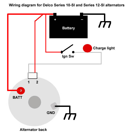
. some of the older ones need to be reved to get them to kick in . If its hooked up like this it should work ? if its one you had kicking around and are not shure of condition any part souce will test it on the bench . I allways tell them its from a 1974 nova  makes them happy.

Wiring diagram for Delco alternator


-- Edited by slim on Sunday 2nd of June 2013 02:57:10 PM


-- Edited by slim on Sunday 2nd of June 2013 03:03:25 PM

__________________
What a long strange trip its been


ST GEORGE, ONT

Status: Offline
Posts: 154
Date:
Permalink  
 

What does alternator out of specification mean as listed above, I just hooked up an internally regulated alternator on my 59 chev and it seems to be charging, red wire to battery from back of alternator , second wire to one of the wires going to the generator light. Now the generator light stays on.

__________________
steve quick


NORTH BAY, ONT

Status: Offline
Posts: 3717
Date:
Permalink  
 

Apparently you can buy a "Low Cut In" internal regulator for alternators, they are used on cop cars and emergency vehichles, that sit idling for long periods.

__________________


MAGNETAWAN, ONT

Status: Offline
Posts: 301
Date:
Permalink  
 

captainq wrote:

What does alternator out of specification mean as listed above, I just hooked up an internally regulated alternator on my 59 chev and it seems to be charging, red wire to battery from back of alternator , second wire to one of the wires going to the generator light. Now the generator light stays on.


 you might have to rev the engine to excite the alternator then the light goes out and its charging. Thats what I have to do with the alternator that replaced the generator on my case dozer.


__________________

if the time ever comes you can't see it, you can lay on your back and do it from underneath.


ST GEORGE, ONT

Status: Offline
Posts: 154
Date:
Permalink  
 

Alls good now, Hooked the wire up using the old generator wire that went to the light and it comes on when i start the car then goes out and its charging. Thanks for the help.

__________________
steve quick


PORT HOPE, ONT

Status: Offline
Posts: 2389
Date:
Permalink  
 

Everyone benifits from this interesting exchange.Thanks guys ,it answered some questions I had as well. Ed

__________________

Any day with friends doin car stuff is a good day

Page 1 of 1  sorted by
 
Quick Reply

Please log in to post quick replies.


Create your own FREE Forum
Report Abuse
Powered by ActiveBoard