Boat winch with a sprocket and chain drive to a sprocket on the engine attachment. Hand crank it to where you want and lock it. Reasonably cheap and easy to do. Princess Auto would have everything that's required to make it work.
If you have ever used an engine stand that has a tube handle that goes thru the hub that is used to rotate the engine you will recognize the short comings of this arrangement.
If you use a cherry picker to lift the engine to install it to the engine stand you will sometimes find it hard to get a good balance on the engine.
Then when you pull the locking pin the engine is either hard to rotate or it wants to get away from you and rotate to where the heaviest part is on the bottom.
Even if you do get an good initial balance on the engine, when you install or remove a heavy part such as the head you will change the center of gravity and then make it difficult to rotate the engine.
There are two solutions. Purchase a $200.00 gear driven engine stand or make one out of your existing stand for $30.00 and some POH that is Parts On Hand.
The parts on hand included a timing chain and the 2 timing gears that go with it. If you don't have a set you can probably get one free at an engine shop because they usually throw them away when they rebuild an engine.
I also used a fence clamp and a 6" piece of angle iron.
I bought a new Harbor Freight engine stand on sale for $39.99 and a cable wench for $29.99.
The next one I make I will use the old Harbor Freight engine stand that is currently holding an engine project in progress.
Again I will use Harbor Freight #5798 2000 lb worm gear cable wench $32.99 regular, $29.99 on sale.
I recommend the worm drive wench because they don't unwind when the engine is left in an unbalanced position.
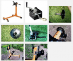
The first thing that I do to the wench is take the bolt holding the spool off and remove the spool and the tube bearing that is inside the spool axle.
Then I push out the bearing and set it aside so that it doesn't get damage.
I then cut the inside of the spool about 1/2" to 3/4" from the gear side. The one in the picture is about 1 1/2" from the gear but the next one will be closer to the gear. See the 3rd picture below.
Do not cut all of the way thru just far enough to go thru the outer spool tube. If you look at the 4th picture you will see an end view showing a tube inside a tube.
You will notice that the tube on mine wasn't centered when it was welded but it won't matter because you are going to weld your small timing gear centered on the smaller 15/16" tube anyway.
I used a lathe to cut mine off because I didn't know how it was put together.
The next one I will chuck in my lathe turning backward and use a 4 1/2" cutoff wheel turning the opposite direction to cut the spool off.
You could use a hack saw but be careful to cut straight because you are going to use that edge of the larger tube as a shoulder to weld the gear to.
When cut thru the non-geared half of the spool will just slide off of the smaller tube because it is not welded at that end.
Then I slid the small timing gear over the shaft and up against the shoulder of the larger tube.
I cut a bushing to center that gear but the next one I will just find something about .2" in diameter to use for spacers to center the gear.
I will then weld the gear to the larger tube and then remove the spacers and weld up the space between the gear and the spool shaft.
Caution should be used so that you don't burn thru the spool shaft while filling the space. Tack weld then weld a little at a time until done.
Then when cool reinstall the shaft being sure to include the timing belt around the gear. I used some anti-seize on the spindle bearing.
I used a galvanized fence bracket to hold the engine stand head shaft tight against the frame and welded the large cam gear onto the shaft. You can see that in the 6th picture.
I was fortunate in that the flange on the gear was just about a perfect match for size with the shaft. I just held it as close to centered and tacked it. After making sure it was as close as I could make it by eye I welded it on.
I then drilled the 6" angle Iron bracket to go onto the wench frame using the spool shaft bolt and the other spacer bolt to hold it to the wench.
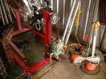
I then installed the timing chain over the large gear on the head and positioned the wench bracket against the side of the frame securing it with a C clamp.
I adjusted the position until the chain was straight and the crank could be turned the 84 turns it takes to rotate the head 360 degrees.
The chain wanted to get tight in one place due to the fact that one or both of the gears weren't perfectly centered. I just tapped the bracket with a small hammer untill it turned without getting tight.
I then welded the bracket to the frame. It could be bolted if you don't want to burn the paint.
The end result is very much like the $200.00 stand except that this stand is not foldable and it takes about 25% more turns to a complete 360 degree rotation.
I will never have an engine get out of control with these engine stands.
-- Edited by Chris Stapley on Tuesday 17th of December 2013 02:33:59 PM