So it has been a while since I made any progress but got a chance today. I am building the trans cross member. Thought I would put some pics here so not to confuse my build page. That and I need/would like to know that I am doing it right.
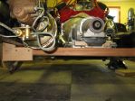
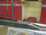
First pic is what I started with. If you look on the left you can see that the booster is below the frame on that side. The wood is holding up the trans right now.
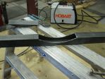
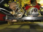
Cut out part of the 2 x 2 to accommodate the booster. Side note, my new welder is in the back ground.
Then tacked a piece of flat stock into place. After that I welded it solid.
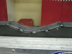
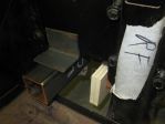
Here is where things went a bit south on me. This pic shows the ends of the level being about 1/4" from the 2 x 2. Need some help here. What did I do wrong? Don't think it is an issue but would like to learn for future reference.
Next I welded in two crush sleeves to bolt the trans mount to this cross member.
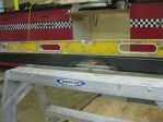
Here is the cross member in place, held up with clamps right now.
To fasten it to the truck frame I was thinking of welding on a 3" long piece of 2 x 2 angle to the frame. Then cutting the end of the 2 x 2 on an angle and bolting the top part of the 2 x 2 square tube to the angle.
So did I do this right or is there something I should have or should do different?
Here is where things went a bit south on me. This pic shows the ends of the level being about 1/4" from the 2 x 2. Need some help here. What did I do wrong? Don't think it is an issue but would like to learn for future reference.
You didn't do anything wrong. Welding will always shrink the side you're working on. Clamping to a solid surface will help, but the metal will still shrink. To fix the problem, heat the opposite side quickly then quench. This will shrink the opposite side and bring your workpiece straight again.
I'm not a fan of anything (ESPECIALLY brake parts) hanging below the frame rails (meaning I'd be searching for a smaller dia booster).
I made my trans cross member similar to the one pictured below. This design worked great for me due to the fact that the bolt heads that thread into the underside of the rubber transmission mount are basically the lowest part of the cross member. This design moves the cross member tubing from below the rubber transmission mount/insulator to behind it and beside it .... getting the cross member up and out of sight and out of harms way.
If what I'm seeing is what I think I'm seeing (in your design), you (and everyone else) will see a bunch of crap dangling below the frame rails when viewing the truck from the side. It's not just an aesthetic thing either .... it's also better for maximum ground clearance when dealing with speed bumps, driveways etc.
I should also add that the cross member you made looks well done, with the dip for the booster and the crush tubes, I just don't like the overall design where it hangs so far below the trans itself as well as below the frame rails.
I apologize if my post is coming off as harsh, I hope you aren't offended then stop posting as a result of my foolishness .... it's just something you might want to take into consideration. If you feel the ground clearance isn't an issue or your running boards will hide the cross member, or you are fine with the look, please just disregard my babbling
-- Edited by chips on Thursday 21st of April 2016 05:08:19 PM
Good fab of the cross member. When setting the engine think about these points:
Is your frame level front to back or at the correct ride height? The carb mount on the intake should be level. I make all my mounts tucked up in the frame.
I have angeliron welded to the crossmember that sits on top of the rails I added and then I used nut certs in the rails to mount the crossmember onto. Pluss think about where your exhaust pipes are going to run.
Have you thought of having the master on the firewall?
On the 57 I welded bungs through the frame to bolt all the mounts I use.
-- Edited by henrys57wagon on Thursday 21st of April 2016 08:25:09 PM
-- Edited by henrys57wagon on Thursday 21st of April 2016 08:28:02 PM
-- Edited by henrys57wagon on Thursday 21st of April 2016 08:28:22 PM
Is your frame level front to back or at the correct ride height? The carb mount on the intake should be level. I make all my mounts tucked up in the frame.
-- Edited by henrys57wagon on Thursday 21st of April 2016 08:28:22 PM
Carb mount level?? I don't think so.
Setting the engine at the proper angle is a complicated process, and it all has to do with the u-joints. Center line of the transmission output shaft, as well as centerline of the rear end pinion will dictate at what angle your engine gets mounted. In a perfect world, you're looking for about 3 degrees of separation between the yokes(not yolks). If you have zero degrees, you'll have vibrations, and if you have too much you u-joint life will suffer. There's a lot more to designing a well built car that just welding parts together
Chevy intake manifolds are machined with a 3-4* angle so the carb sits level when the back of the engine down.
With the carb mounting flange level the engine/ trans will be 3-4 degrees pointing down. The fixed dif that Martin is using should be set at 1-2* up, leaf sprung cars should be set at 0*. I have used this method on quite a few cars without issues.
Here is something to look at, there are a lot more:
Trying this for responding. I am out of town so using my phone. You guys have raised good points. On this rod the front bumper and sheet metal are the lowest points. The brake lines you see are at least 3-4" above that. The carb plate is set level front to back and side to side. This allows for some pinion angle. For exhaust pipes it will be tight but I think it is doable. The hard part is getting past the rear end.